Sheet metal stamping is a crucial process in the manufacturing industry, enabling the creation of intricate and precise components. In this post, we will delve into the intricacies of bead geometry and binder forces, exploring how they impact the overall stamping process. We’ll also address the specific issue of fixing fractures without creating undesirable consequences such as buckles or ghost lines.
Beads & Their Role in Restraint

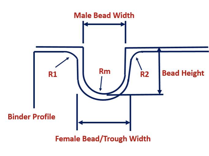
The stamping process allows us to consistently produce a permanent, new shape through stretching and work hardening sheet metal blank over a component’s die geometry. The bead geometry plays a very important part in maintaining process stability. Beads produce restraining forces that control material flow from the binder to be drawn into the die work envelope; this control helps prevent metal fractures while ensuring sufficient draw-in to successfully achieve the part geometry. A combination of work hardening from the sheet metal bending around the bead radii, as well as the sliding friction, “restraining force,” is generated to control metal flow from the blank edge.
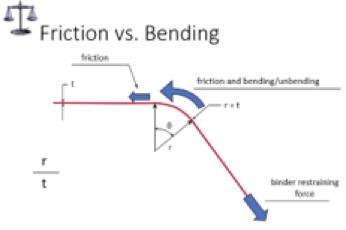
Friction & Bending
Two key factors contribute to the restraining force produced by beads: friction and bending. The process of sheet metal bending around the bead radii results in work hardening, which increases the yield strength of the material. This increased yield strength, in turn, generates higher frictional forces that help control the flow of material from the blank edge.
Radii Influence
In the sketch above, we understand that R1 and R2 radii influence bead setting forces as the bead is set to depth during binder closure. The smaller these radii, the greater the setting force. Increased bending forces will also produce a substantial increase in the friction generated by material sliding into the die to form the part shape.
The Impact of Yield Strength

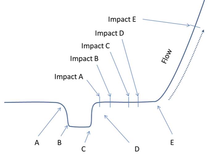
As the blank is drawn through the bead into the die from the addendum area, the bending and unbending action alters (increases) the yield strength of the displaced sheet metal. The original Y.S. of the blank is lower than the Y.S. of the material as it bends around the male bead radius. The second bend and unbend action further elevates the Y.S. of the material and additional bending force, generating higher frictional forces, will be produced in holding the material down and sliding over R2. If R1 and R2 are the same size radii with identical surface finish, R2 will be responsible for a larger portion of the restraining force as the blank is being drawn into the part.
The increase in Yield Strength that each radius will generate is a function of not only the bead radius but also the sheet metal’s N-value or work hardening exponent. A higher “N-value will require less severe bead radii and lower binder closure tonnage requirements. Larger radii and lower binder closure forces will translate into lower friction and less maintenance from the associated reduction in bead wear.
Fixing Fractures Without Creating Buckles or Ghost Lines
Now that we’ve explored the role of beads and restraining forces, let’s address a specific problem that arises in sheet metal stamping: fixing fractures without causing unwanted consequences.
The Split Dilemma
A Body-Side Outer develops a split in the C-pillar and header intersection area. In a frantic move to eliminate the split, someone adjusts the equalizers on the inner binder or “pillow” to get more metal to flow in that area. The split goes away, and production starts back up. The split, which was caused by high localized strain, might have gone away, but this move could have caused another issue, a buckle on the class A surface. There are many ways die-makers have tried to correct this exact situation. They might have ground the beads on the inner and/or outer binder, while others may have just changed the Nitrogen pressure on the inner pillow (if constructed this way).
Balancing Inner and Outer Binder Forces

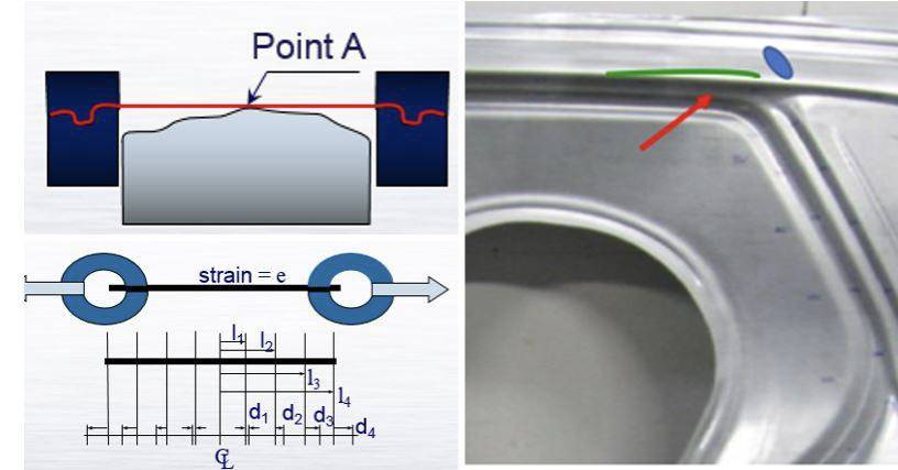
Reducing the internal binder force may resolve the split problem, but we can’t let the restraining forces between the inner and outer binders become too unbalanced. As the inner part restraining forces are reduced to eliminate the split and the outer binder forces, remain unchanged, material will begin to be displaced over the door opening radius (Point A). The resulting metal movement (green line in the photo below) will produce a ghost, shadow, or double draw line (depending on your facility’s terminology), which may go unnoticed until parts are painted after assembly.
Solutions to Prevent Metal Displacement

To prevent material displacement over the product radius, it’s logical to consider rebalancing the binder forces. However, lowering the outer binder forces is accompanied by a reduction in the overall work hardening and dent resistance of the door header area. Without adequate stretch in this region of the part, the draw depth and length of line differential between the door opening and shallower “C” pillar may produce a buckle or low in the area shown by the blue area above.
In this case, it may be necessary to create a restraining force by roughening the door opening radius (above the fracture area) as the internal binder restraining force is reduced. By creating a less polished product radius, friction will locally increase, allowing for the necessary increase in material displacement from the door opening cutout without reducing the outer binder restraining forces.
If metal displacement over the door opening radius is still evident, a smaller product radius at the door opening line may be required. This change will increase bending restraining forces and friction, preventing material from being drawn over the product radius onto the header, the product show area. Care during welding and radius refinishing is required to prevent a weld line show through on the final product.
OPTIMIZE SHEET METAL PROCESSES WITH HELP FROM PHOENIX
Sheet metal stamping is a complex process that relies on various factors, including bead geometry and binder forces. Understanding how these elements interact is essential for maintaining process stability and producing quality components. Additionally, addressing specific issues such as fractures without causing undesirable consequences requires a thoughtful and balanced approach to binder forces. By implementing these insights, manufacturers can optimize their sheet metal stamping processes and achieve exceptional results.
If you’re interested in learning how The Phoenix Group can drive improvement at all levels of your organization, contact us today.


